1. What is the OSI model?
The OSI (Open Systems Interconnection) model is an international reference framework developed by the International Organization for Standardization (ISO) to standardize how different network systems communicate with one another. The OSI model divides the data transmission process into 7 independent layers, each responsible for a specific group of functions and interacting only with the adjacent layers directly above and below it.
The OSI model emerged in the late 1970s, when network equipment manufacturers were developing products that were incompatible with one another. This situation created significant challenges in connecting and integrating networks from multiple vendors. In 1984, ISO officially published the OSI model as an international standard, establishing a common language that technical professionals could use to discuss and resolve network issues in a unified manner.
A key strength of the OSI model is its clear separation of responsibilities across each component in a network system. Network engineers can pinpoint exactly which layer a fault occurs in, rather than having to inspect the entire system. In addition, the layered architecture allows developers to build new protocols and technologies without needing to modify other layers.
2. Data encapsulation and decapsulation in the OSI model
One of the most important concepts when studying the OSI model is the process of data encapsulation and decapsulation. This is the actual mechanism that explains how data is prepared, transmitted, and recovered intact across a network system.
2.1 Encapsulation when sending data
When sending data, information begins at Layer 7 (Application) and travels downward to Layer 1 (Physical). Each layer does not modify the data content from the layer above; it simply adds a header containing its own control information. As a result, the original data is progressively wrapped in multiple header layers, much like placing a letter in an envelope, then boxing it up, then attaching a shipping label.
- Layer 7 Application: generates the original data
- Layer 6 Presentation: adds encoding and format information
- Layer 5 Session: adds a session label (session ID)
- Layer 4 Transport: splits data into segments, adds source and destination port numbers and sequence numbers
- Layer 3 Network: encapsulates into packets, adds source and destination IP addresses
- Layer 2 Data Link: encapsulates into frames, adds source and destination MAC addresses, and appends a CRC for error checking
- Layer 1 Physical: converts frames into a bit stream and transmits them over the physical medium
Example: When you type a website address into your browser and press Enter, Layer 7 creates an HTTP GET request, Layer 6 encrypts it using TLS, Layer 5 establishes a session with the server, Layer 4 segments the data into TCP segments sent to port 443, Layer 3 encapsulates them into packets with the server's destination IP address, Layer 2 encapsulates them into Ethernet frames with the gateway's MAC address, and Layer 1 converts everything into electrical or optical signals transmitted over the network cable.
2.2 Decapsulation when receiving data
On the receiving side, each layer reads and processes only the header that was added by its counterpart on the sending side, then removes that header and passes the remaining data up to the layer above. Data is progressively stripped layer by layer from bottom to top until the application receives the original content intact.
- Layer 1 Physical: receives the physical signal, converts it into a bit stream, and passes it to Layer 2
- Layer 2 Data Link: reads the destination MAC address, checks the CRC for errors, strips the frame header, and passes the packet to Layer 3
- Layer 3 Network: reads the destination IP address, strips the IP header, and passes the segment to Layer 4
- Layer 4 Transport: reads the port number, reassembles segments in the correct order, strips the TCP header, and passes the data to Layer 5
- Layer 5 Session: identifies the corresponding session, strips the session header, and passes the data to Layer 6
- Layer 6 Presentation: decrypts the data, converts it into a format the application can read, and passes it to Layer 7
- Layer 7 Application: receives the original data intact and processes it according to application logic
Example: Continuing from the previous example, when the signal arrives at the server, Layer 1 converts it into bits, Layer 2 checks the CRC and confirms the frame was not corrupted in transit, Layer 3 confirms the destination IP address matches this server, Layer 4 reassembles the TCP segments in the correct order and sends an ACK back to the client, Layer 5 identifies which active session this belongs to, Layer 6 decrypts the TLS payload, and Layer 7 receives the intact HTTP GET request, at which point the web application begins processing it to return a response.
3. Summary table of the 7 OSI layers
| Layer | Main Role | Example Protocols/Standards | Typical Devices |
| 7. Application | Service interface for applications/users | HTTP/HTTPS, DNS, SMTP, IMAP, FTP, Telnet | Web applications, mail clients |
| 6. Presentation | Encryption, compression, format conversion | TLS/SSL, JPEG, MPEG, ASCII/Unicode | Libraries in OS/applications |
| 5. Session | Establish/maintain/synchronize sessions | NetBIOS, RPC, PPTP* | System software |
| 4. Transport | End-to-end connection, error/flow control | TCP, UDP | Endpoints (servers, clients) |
| 3. Network | Logical addressing & inter-network routing | IP (IPv4/IPv6), ICMP, OSPF, BGP | Router, L3 switch |
| 2. Data Link | Frame packaging, MAC addressing, VLAN | Ethernet (MAC/LLC), PPP, 802.1Q, 802.1X | Switch, bridge, NIC |
| 1. Physical | Bit transmission over physical medium | UTP, fiber optic cables, 1000BASE-SX, RS-232 | Cables, hubs, repeaters, RJ-45 connectors |
4. Detailed Analysis of the 7 OSI Model Layers
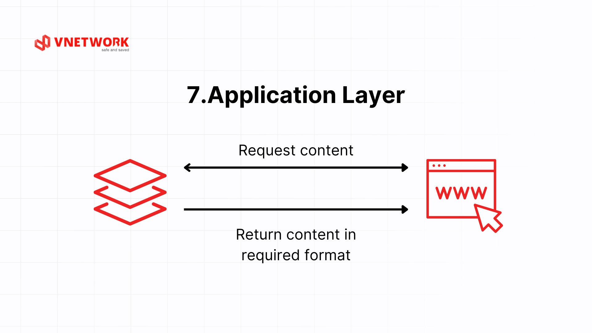
4.1 Layer 7: Application Layer
Data unit: Data.
The Application layer is the topmost layer, providing a direct interface between network applications and end users. It is the layer users interact with most frequently, even though they never see it directly.
Common protocols at Layer 7: HTTP/HTTPS is the foundation of the World Wide Web; SMTP sends email while POP3/IMAP retrieve it; FTP/SFTP handle file transfers, with SFTP adding security; DNS resolves domain names to IP addresses; and DHCP automatically assigns IP addresses to devices on a network.
Example: when you type a website address into your browser, a DNS resolver translates the domain name into an IP address. The browser then uses HTTPS to send an HTTP GET request to the server, receives HTML/CSS/JavaScript in response, and renders the page.
The Application layer is also where the most sophisticated attacks take place. SQL Injection, XSS (Cross-Site Scripting), and vulnerabilities in the OWASP Top 10 all operate at Layer 7 because they directly exploit application logic. This is why WAFs operating at Layer 7 serve as a critical protection layer for enterprise web applications, complementing security measures at lower layers.
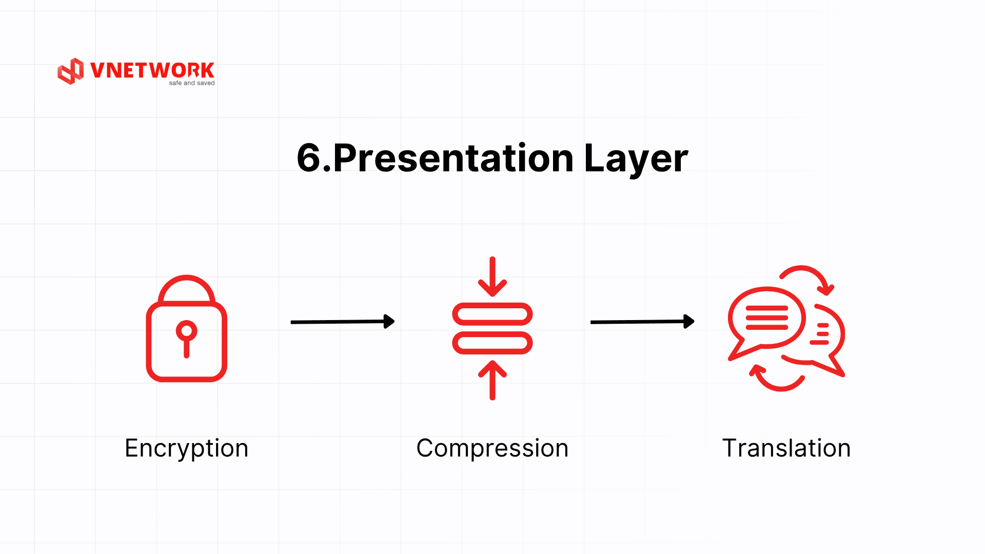
4.2 Layer 6: Presentation Layer
Data unit: Data.
The Presentation layer acts as a translator, converting data between different formats so that two systems can understand each other even when using different storage structures. The Presentation layer handles three primary tasks: format conversion, encryption and decryption, and data compression and decompression.
Regarding format conversion: one system may use ASCII to represent characters while another uses EBCDIC. The Presentation layer ensures both sides read the data accurately. The same applies to little-endian and big-endian differences when exchanging integers between systems with different CPU architectures.
Regarding encryption: in the theoretical OSI model, the encryption function is attributed to Layer 6. It is worth noting that TLS/SSL in actual implementations does not reside entirely within a single layer but spans multiple layers depending on one's perspective. When studying the OSI model theoretically, encryption and decryption are described as occurring at Layer 6, helping learners understand that data security is a distinct processing step before data moves down to Layer 4. Formats such as JPEG, PNG, MPEG, and ZIP also operate at this layer.
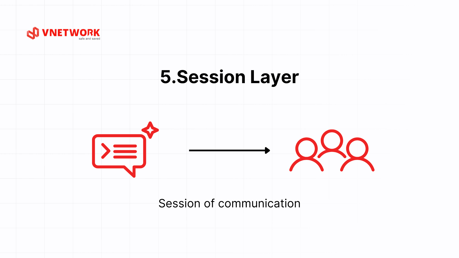
4.3 Layer 5: Session Layer
Data unit: Data.
The Session layer manages the establishment, maintenance, and termination of communication sessions between two applications. It ensures that data from different applications on the same machine is not mixed together.
Synchronization is a key differentiator of Layer 5. The Session layer allows checkpoints to be placed throughout the data transfer process. If the connection drops, the session can resume from the nearest checkpoint rather than restarting from the beginning. The clearest example of this is large file transfers over SFTP: if the connection is lost midway, the session can resume from where transmission left off rather than starting over.
Another practical example is a database session. When an application opens a connection to a MySQL server, Layer 5 manages the lifecycle of that session: authentication, connection parameter negotiation, handling unexpected disconnections, and automatic reconnection as needed. RPC (Remote Procedure Call) is another typical example, enabling functions to be called on a remote machine as if they were local calls, with Layer 5 managing the entire lifecycle of that communication session.
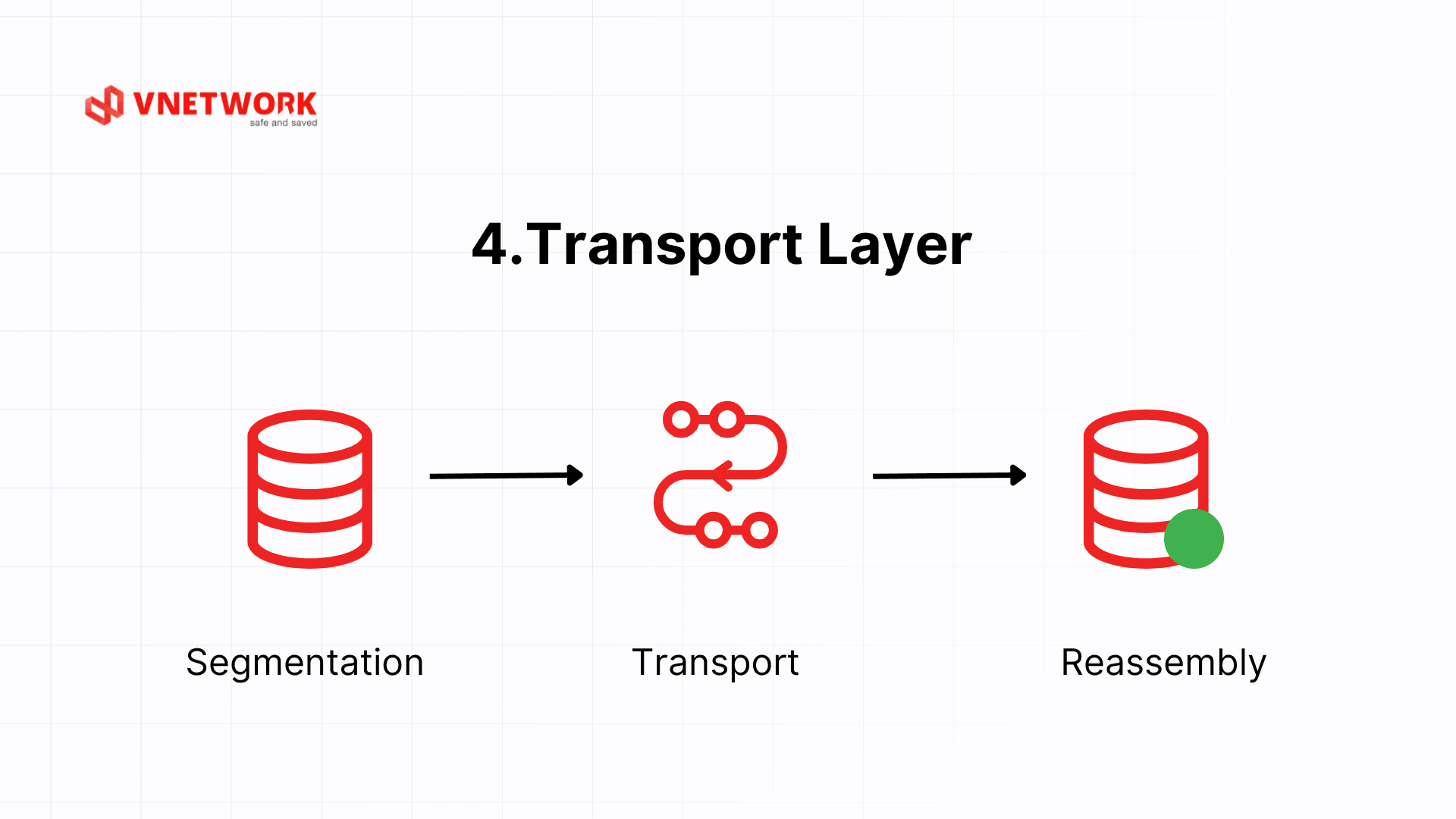
4.4 Layer 4: Transport Layer
Data unit: Segment.
The Transport layer ensures reliable data transfer between applications on two end devices. It is the first layer that truly concerns itself with end-to-end connectivity, rather than handling only individual packet forwarding steps.
TCP (Transmission Control Protocol) provides a reliable connection through a three-way handshake and acknowledgment mechanism, guaranteeing data ordering and integrity. UDP (User Datagram Protocol) prioritizes speed over reliability and is suitable for real-time applications such as video streaming or voice calls.
The concept of ports allows multiple applications to share a single network connection. For example, HTTP uses port 80, HTTPS uses port 443, and SSH uses port 22. When downloading a large file via TCP, the protocol splits the file into thousands of segments, numbers them sequentially, and requests retransmission only of the segments that were lost, rather than the entire file.
TCP's sliding window mechanism allows the sender to transmit multiple segments before requiring acknowledgment, increasing bandwidth efficiency. The window size can grow progressively over time (TCP slow start) to probe the optimal throughput of the link, avoiding the transmission of too much data at once that could cause congestion.
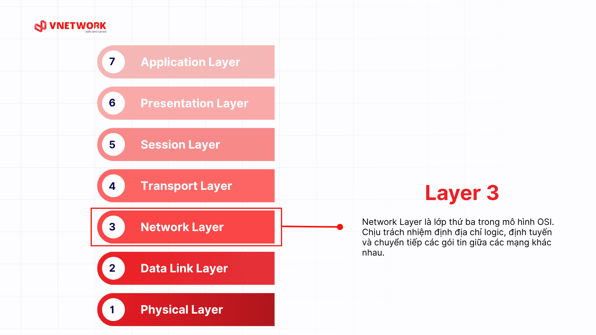
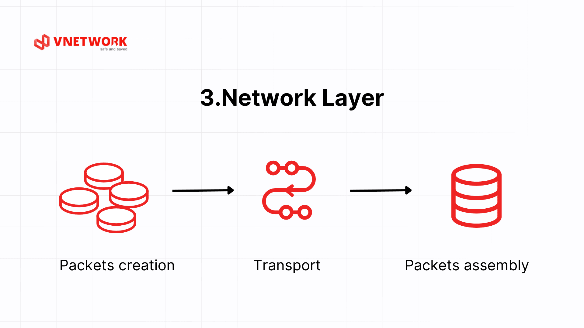
4.5 Layer 3: Network Layer
Data unit: Packet.
The Network layer extends communication capability from local area networks to the global scale by providing routing services between different networks. It is the first layer to use logical addressing (IP addresses) and to support routing.
IPv4 uses 32-bit addresses (e.g., 192.168.1.1), while IPv6 uses 128-bit addresses to address the problem of IPv4 exhaustion. ICMP provides network status information and is used by the ping command. Routing protocols such as OSPF and BGP enable routers to exchange routing table information.
The router is the primary device at Layer 3, capable of connecting multiple networks and determining the path for each packet. A Layer 3 switch combines switching and routing functions and is commonly used in large internal networks.
An important concept at Layer 3 is TTL (Time to Live). Each packet carries a TTL value that is decremented by 1 each time it passes through a router. When the TTL reaches 0, the packet is discarded and the router sends an ICMP "Time Exceeded" message back to the source. This mechanism prevents packets from looping indefinitely in the network in the event of a routing failure.
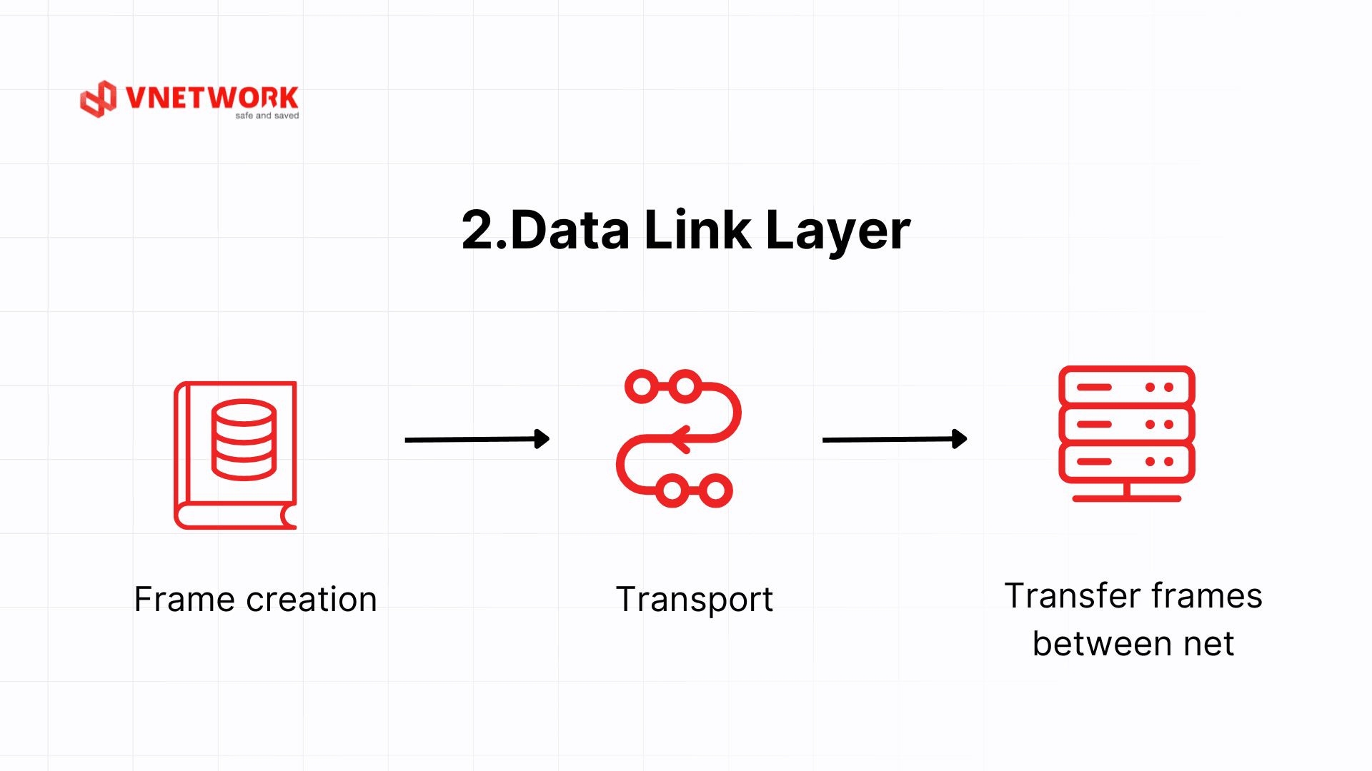
4.6 Layer 2: Data Link Layer
Data unit: Frame.
The Data Link layer transforms raw bits from the Physical layer into structured and meaningful data frames. It is the first layer that actually processes data rather than simply transmitting signals.
The Data Link layer performs three core functions. Framing organizes data into frames with a header containing source and destination MAC addresses. Error control is carried out by computing and verifying a CRC (Cyclic Redundancy Check). Flow control ensures the sending device does not overwhelm the receiving device.
The switch is the most characteristic device of Layer 2. A switch maintains a MAC address table, learns the addresses of connected devices, and forwards frames precisely to the destination port rather than broadcasting like a hub. For example, in an office LAN, when computer A sends data to computer B, the switch reads the destination MAC address in the Ethernet frame and forwards it only to the port connected to computer B.
The Data Link layer is also divided into two sublayers. The LLC (Logical Link Control) sublayer manages communication rules and error control. The MAC (Media Access Control) sublayer governs access to the physical transmission medium, determining which device is allowed to send data at any given moment to prevent collisions. In Wi-Fi networks (802.11 standard), the MAC sublayer plays a critical role in handling contention for wireless channel access among multiple devices.
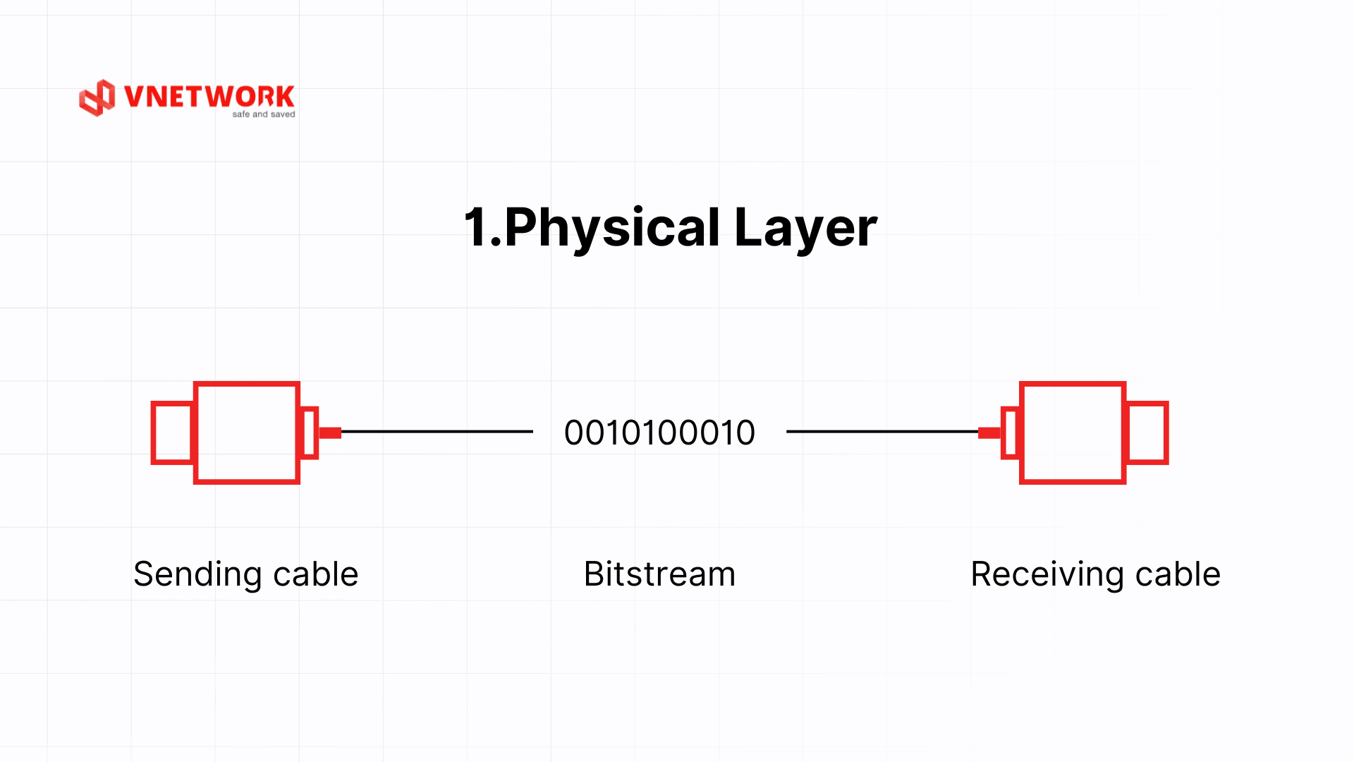
4.7 Layer 1: Physical Layer
Data unit: Bit.
The Physical layer is the foundation of the entire OSI model, responsible for transmitting data at the bit level across physical media. The Physical layer does not concern itself with the meaning of the data; it focuses solely on converting bits into physical signals (electrical, optical, or radio) and vice versa.
The Physical layer defines the electrical, mechanical, and functional characteristics of the physical interface: voltage levels representing 0 and 1, transmission speed, connector pin configurations, and cable types. Standards such as 1000BASE-T (Gigabit Ethernet over copper), 1000BASE-SX (fiber optic), and RS-232 (serial connection) are all defined at this layer.
Representative devices: hubs function as multi-port repeaters, amplifying and distributing signals; repeaters extend transmission range; and various network cables such as UTP, fiber optic, and RJ-45 connectors.
One important point: the Physical layer does not distinguish between meaningful and meaningless data. It only knows how to move 0s and 1s. If a physical cable is damaged, experiencing interference, or disconnected, the entire network stack above it will stop functioning even if all other layers are correctly configured. This is why engineers always check the Physical layer first when debugging a network issue.
5. Comparing the OSI model and TCP/IP
The OSI (Open Systems Interconnection) model and TCP/IP (Transmission Control Protocol/Internet Protocol) model are the two most popular network architectures today. Both are used to describe how data is transmitted between devices in a network system. However, they differ in layer organization, application scope, and design goals.
| Comparison Criteria | OSI Model (7 layers) | TCP/IP Model (4 or 5 layers) |
| Number of layers | 7 layers: clear, separate functions | 4 or 5 layers, simplified for practical implementation |
| Design goal | Standardize communication for education, research | Designed to serve global Internet operations |
| Application scope | Theoretical, popular in education | Directly applied in real network systems |
| Application layer division | Application, Presentation, Session | Combines 3 above layers into Application |
| Popular protocols | HTTP, SMTP, TLS, TCP, IP, Ethernet... | HTTP, DNS, TCP, UDP, IP, Ethernet... |
| Layer detail level | High – beneficial for learning, modeling | Implementation-focused – convenient for system deployment |
| Suitable for purpose | Teaching, network certification, network troubleshooting | Real network design, programming and service deployment |
Advantages and Disadvantages of OSI Model
Advantages:
- Clear layering makes it easy to learn, remember, and analyze problems
- Suitable for teaching, research, network certification exams (CCNA, CompTIA...)
- Supports layered security thinking (defense-in-depth)
Disadvantages:
- Does not accurately reflect how protocols operate in real Internet applications
- Some layers like Session and Presentation are not clearly separated in modern applications
- Rarely used as a standard in practical implementation
Advantages and Disadvantages of TCP/IP Model
Advantages:
- Widely applied on the Internet and in practical network deployment
- Compact, simple structure, easy to integrate and develop
- Suitable for how modern protocols like HTTP, TLS, QUIC operate
Disadvantages:
- Lacks detail in some layers (no separate Presentation and Session)
- Less suitable for teaching purposes or in-depth layer error analysis
6. Applying the OSI model to enterprise network security
The OSI model is not merely an academic tool. In practice, it serves as the foundation for building a layered security strategy, enabling organizations to address threats at each level of the network system.
6.1 Analyzing DDoS attacks by OSI layer
DDoS attacks can target multiple layers within the OSI model, and each type requires a distinct mitigation approach.
- Layer 3 (Network): IP flooding and ICMP floods send large volumes of packets to saturate bandwidth and overload routers.
- Layer 4 (Transport): SYN floods exploit the TCP three-way handshake, exhausting the server's connection resources.
- Layer 7 (Application): HTTP floods send millions of legitimate-looking HTTP requests with the intent of overwhelming the application. This is the hardest type of Layer 7 attack to detect because the traffic appears normal.
Understanding which layer is under attack allows the technical team to select the precise mitigation measure, rather than applying broad countermeasures across the entire system indiscriminately.
6.2 At which OSI layers do firewalls and WAFs operate?
Network security solutions operate at different OSI layers depending on their level of protection:
- Traditional firewalls (Packet Filter Firewall): operate at Layers 3 and 4, filtering packets based on IP addresses, port numbers, and protocols (TCP/UDP).
- WAF (Web Application Firewall): operates at Layer 7, analyzing the content of each HTTP/HTTPS request to detect and block attacks such as SQL Injection, XSS, and the OWASP Top 10.
- WAAP (Web Application and API Protection): a next-generation solution that protects both web applications and APIs, combining WAF with bot management and DDoS protection across multiple layers.
6.3 Network troubleshooting process using the 7 OSI layers
The OSI model provides a systematic troubleshooting workflow. Engineers should check from the lowest layer up to progressively narrow the scope of the fault:
- Layer 1: check physical cables, port status indicators, and link signals. Key question: is the cable connected and is the link light on?
- Layer 2: check MAC addresses, VLANs, and switch configuration. Key question: are frames being forwarded to the correct port?
- Layer 3: check IP addresses, subnet masks, default gateways, and the routing table. Key question: can the default gateway be pinged?
- Layer 4: check ports, TCP connection state, and firewall rules. Key question: does a telnet or netcat connection to the destination port succeed?
- Layer 5: check session state, session timeouts, and authentication. Key question: is the session dropping unexpectedly?
- Layer 6: check SSL/TLS certificates, data formats, and encryption. Key question: are there certificate errors or decryption failures?
- Layer 7: check application configuration, error logs, and the protocol in use. Key question: is the application reporting any specific errors?
Applying this process helps technical teams identify the root cause of an issue faster and avoid unstructured, scattered investigation. For organizations looking to build a layered security strategy (Defense in Depth), the OSI model provides the reference framework for determining which layer requires a security solution.
7. The OSI model in the context of modern networking
Although the modern Internet runs on the TCP/IP model, the OSI model retains its value for analyzing and explaining new networking technologies. Trends such as cloud computing, IoT, and 5G networks can all be examined through the lens of the OSI model.
7.1 OSI and cloud computing
In cloud architectures, the OSI model helps clarify security responsibilities between cloud service providers and their customers. Layers 1 through 3 are typically managed by the cloud provider (physical infrastructure, switches, routers). Layers 4 through 7 fall within the customer's security responsibility, depending on the deployment model (IaaS, PaaS, SaaS). Understanding this boundary helps organizations pinpoint exactly which layers require additional security measures.
7.2 OSI and IoT
IoT (Internet of Things) devices are fundamentally network devices with distinct characteristics: limited hardware, unstable connectivity, and massive scale. The OSI model helps IoT engineers design optimized communication protocols for each layer: selecting the appropriate physical transmission standard (Zigbee, LoRa at Layer 1), handling addressing and routing for millions of devices (Layer 3), and securing sensor data before transmission to the cloud (Layers 6 and 7).
7.3 OSI and HTTP/3 with QUIC
HTTP/3 uses QUIC instead of TCP as its transport protocol. QUIC runs over UDP (Layer 4) but implements its own error control and connection management at the application layer, blurring the boundary of responsibilities between Layer 4 and Layer 7 as defined by the traditional OSI model. This is a prime example of how the OSI model serves as a theoretical reference framework; in practical protocol development, those boundaries can be more flexible.
8. Conclusion
The OSI model, with its 7 clearly defined layers, remains an indispensable tool for understanding how computer networks fundamentally operate. From transmitting bits over cables at Layer 1 to processing user requests at Layer 7, each layer plays a specific role and is tightly coupled with its adjacent layers. More importantly, the OSI model provides the foundation for building a layered security mindset, enabling organizations to analyze and resolve issues precisely at the right point rather than applying vague, generalized fixes.
For organizations seeking to build a comprehensive and secure network infrastructure, VNETWORK's multi-layer security solutions, including WAF, WAAP, and professional anti-DDoS services, protect web applications from Layer 3 through Layer 7. Contact VNETWORK's technical team for a consultation tailored to your organization's scale and industry.
Frequently asked questions about the OSI model
1. Which OSI layer does each network device operate at?
- Hub: Layer 1 (Physical); simply amplifies and distributes electrical signals.
- Switch: Layer 2 (Data Link); uses MAC addresses to forward frames to the correct port. A Layer 3 switch can also route at Layer 3.
- Router: Layer 3 (Network); uses IP addresses to route traffic between different networks.
- Firewall/WAF: Layer 3 through Layer 7, depending on the type; filters traffic at multiple levels.
2. Which protocol belongs to which OSI layer?
- Layer 7 Application: HTTP, HTTPS, DNS, SMTP, FTP, Telnet
- Layer 6 Presentation: TLS/SSL (in the theoretical model), JPEG, MPEG, ASCII
- Layer 4 Transport: TCP, UDP
- Layer 3 Network: IP (IPv4/IPv6), ICMP, OSPF, BGP
- Layer 2 Data Link: Ethernet, PPP, 802.11 (Wi-Fi)
3. Why is the OSI model important for network security?
The OSI model provides an analytical framework for identifying security threats at each layer. DDoS attacks can target Layer 3, Layer 4, or Layer 7, and each type requires a different mitigation approach. Understanding which layer is under attack enables organizations to deploy security solutions with precision and build a more effective multi-layered defense strategy.
4. What is the key difference between the OSI model and TCP/IP?
The OSI model has 7 layers, with each function clearly separated, making it well-suited for teaching and troubleshooting. The TCP/IP model has 4 layers, streamlined for practical deployment and serving as the backbone of the modern Internet. In practice: use OSI for analysis and debugging; use TCP/IP for network system deployment and programming.
5. What is encapsulation in the OSI model?
Encapsulation is the process by which each layer in the OSI model adds a header containing control information to the data before passing it to the layer below. When sending, data travels from Layer 7 down to Layer 1, with each layer wrapping it in an additional header. When receiving, the reverse process (decapsulation) occurs: each layer reads and removes its header before passing the data up to the layer above.